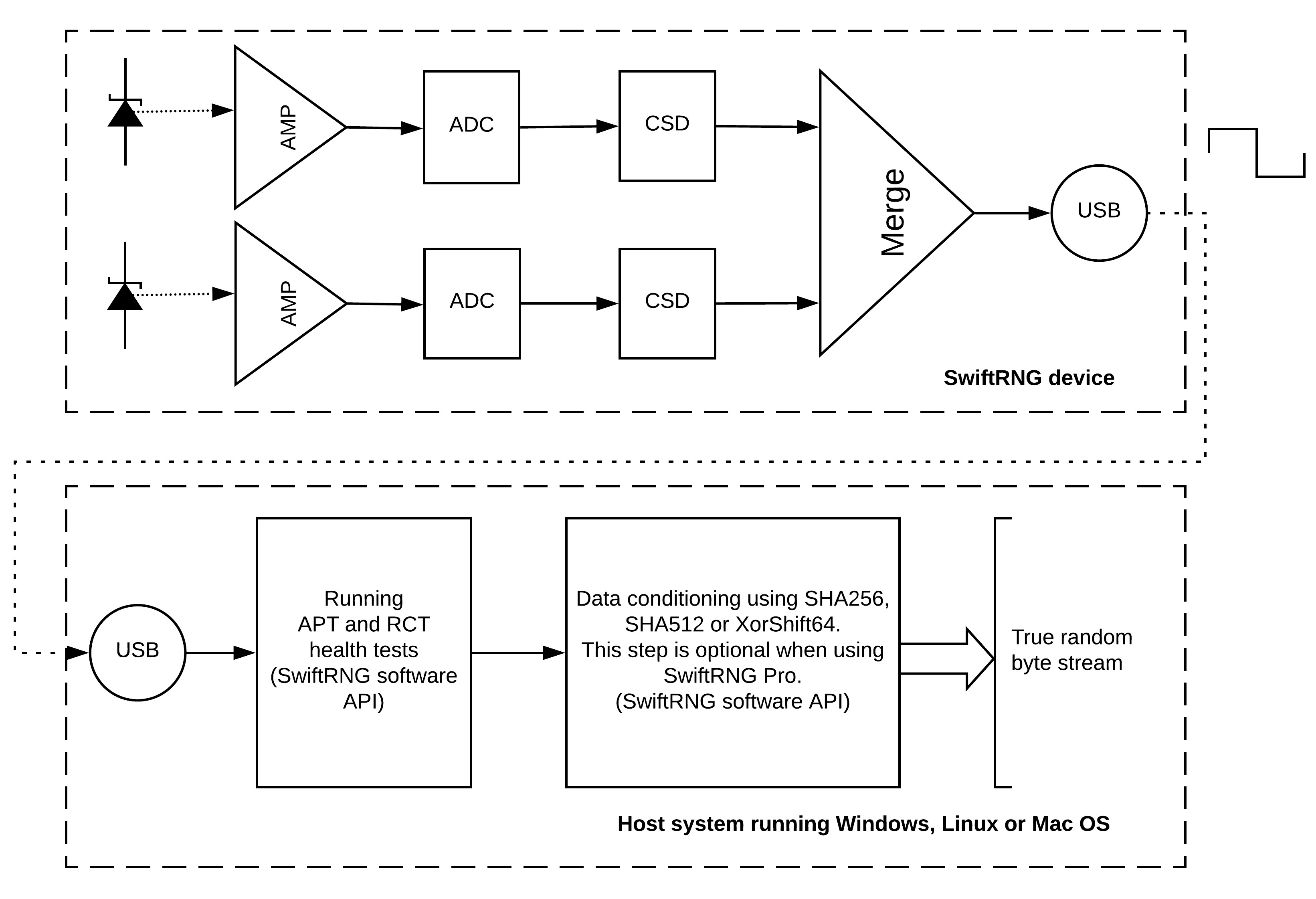
In the first installment of our SwiftRNG In Depth series, we will explore how each SwiftRNG device generates true random numbers from Zener diodes. The diagram below is a schematic representation of a SwiftRNG device in the top-half, and a host computer in the bottom-half. We will be going over the different parts of this diagram below.

Step 1: Noise production
Each SwiftRNG contains two reverse-biased Zener diodes, which are shown in the top-left of the diagram. These Zener doides generate noise from the avalanche breakdown effect. The Zener diode is a semiconductor component. In other devices, Zener diodes are often used in DC circuits as voltage regulators or to provide voltage references.
The frequency range of the electrical noise generated by a Zener diode depends on the component manufacturer, breakdown voltage and physical dimensions. Depending on the diode, avalanche breakdown is observed at above 6-8 volts, and the electrical noise generated in such components is strong enough to be measured, and has the characteristics of randomness. This makes Zener diodes a candidate for a good noise source in hardware random number generators.
Avalanche diodes such as Zener diodes generate large quantities of radio frequency noise and are widely used for RF measurements. After extensively testing noise sources based on Zener diodes, we have found no evidence of any quality deterioration over time.
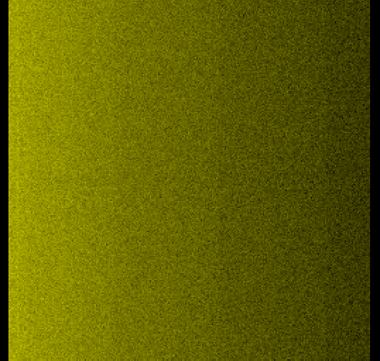
The following is a spectrum analyzer waterfall that was created by sampling the noise generated from a Zener diode used in SwiftRNG. The chart shows the magnitude of the noise signal versus frequency within the frequency range of 10 MHz to 54 MHz. It shows a smooth distribution of the frequencies of the noise.

Step 2: Noise amplification
Each of the two Zener diodes is connected to an amplifier (labeled AMP in the diagram), which amplifies the electrical noise. At this point, the noise data is still in analog form.
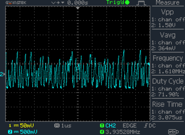
The following plot was generated by an oscilloscope that measured the amplified random electrical analog signal generated by a Zener diode.

Step 3: Conversion to digital form
The result of noise amplification from each amplifier is then sent to an analog-to-digital converter (labeled as ADC in the diagram). The ADC converts the analog signal into a digital stream of random bytes. Each Zener diode, amplifier, and converter together form an independent noise source, and each SwiftRNG device contains two of these independent noise sources.
Step 4: Digitized value validation
Digitized random values from each noise source is then sent to a continuous self-diagnostics component (labeled as CSD in the diagram), which validates the random values. The component performes frequency analysis, and checks for deteriorations or malfunctions in the noise source. The result of this analysis is reported in the overall generator status code.
Step 5: Byte stream merge
The independent byte streams produced are then merged into one stream using logical XOR and shifting operations. The final random bytes produced by SwiftRNG Pro have excellent random characteristics, a very low BIAS and don’t require any additional whitening processing. This is shown in the component named ‘Merge’ in the diagram.
Step 6: USB transmission
The resulting bytes are transmitted to the host system using SwiftRNG software API through USB interface. A monitoring logic built into the software API of the SwiftRNG checks the quality of the final random bytes produced. This is done by continuously running Repetition Count tests and Adaptive Proportion tests, as specified by NIST Special Publication (SP) 800-90B.

Step 7: Post-processing
In the final step, the random bytes are fed to a conditional component by applying SHA256, SHA512 or XorShift64 post processing method. This data conditioning step is optional for SwiftRNG Pro.
The final bytes produced can be accessed with the supplied SwiftRNG software kit on Windows, Linux and macOS.